Vertical milling machine BHEuniversalfor aeronautics3-axis
Add to favorites
Compare this product
fo_shop_gate_exact_title
Characteristics
- Spindle orientation
- vertical, universal
- Other characteristics
- for aeronautics, 3-axis
- X travel
Min.: 2,200 mm
(86.61 in)Max.: 6,200 mm
(244.09 in)- Y travel
Min.: 1,700 mm
(66.93 in)Max.: 3,600 mm
(141.73 in)- Z travel
Min.: 700 mm
(27.56 in)Max.: 1,300 mm
(51.18 in)- Power
Min.: 0 kW
(0 hp)Max.: 25 kW
(34 hp)
Description
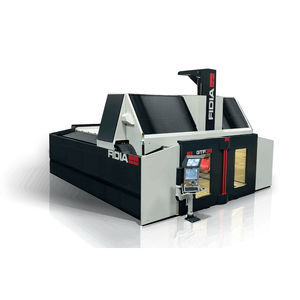
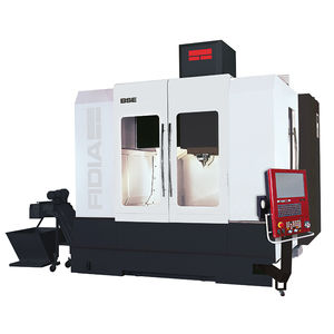
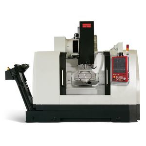
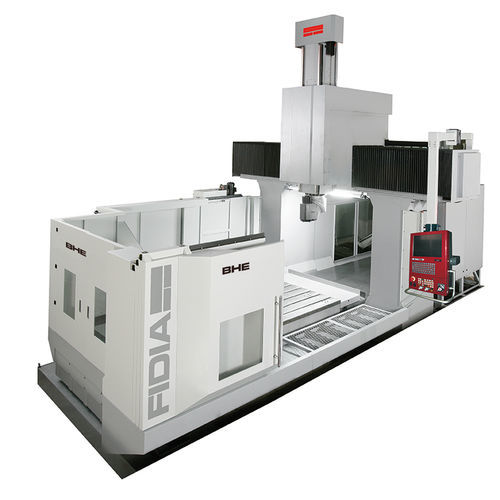
The BHE Bridge type machines are designed for use in general machining and tooling, but also for the aviation industry. The structures, extremely rigid, allow both the use of heads with very high torque and 3 axis high speed milling technology.
The accuracy and the dynamics of the machine guarantees excellent results in conventional machining but also in high-performance machining. High performance and efficiency are characteristics of this machine line, aimed at customers looking for reliable and durable technology
Configurable Z axis Trave
Z vertical axis may have travels with 700/900/1100/1300 mm with a RAM structure measuring 380x380mm or 420x420mm.
Large capacity & easy access
Tables from 2x1.7m to 6x3.1m, with a load capacity from 8,000 kg to 28000 kg.
Opening the front door allows easy access for loading and unloading of parts.
Automatic Tool Change
Automatic Tool changer up to 180 positions.
Wide range of Spindles and milling heads
3 axis spindle from 6000rpm to 15000 rpm
Universal heads with BT#50 or ISO50 3500 rpm.
STRUCTURE
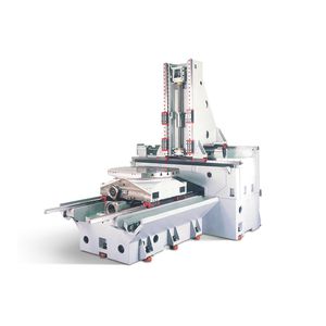
BHE machines are manufactured entirely in cast iron parts: base, columns, traverse and RAM (Z axis) of size 380x380mm, are designed with FEM system.
X axis with 4 linear guides (models with Y > 1700mm)
4 linear guides are mounted in the machine bed to grant excellent dynamics and max payload on the table:
2 Roller guidesa
2 Linear guides
Y axis with the exclusive solution of 3 roller guides
The movement of the Y drive is accomplished through 3 linear roller guides to ensure maximum rigidity and accuracy even in movements at high speed:
2 Roller guides mounted on the top of the traverse
Catalogs
Related Searches
- Aeronautic milling machine
- Milling machine
- CNC milling machine
- Multi-axis milling machine
- Vertical milling machine
- 3-axis milling machine
- Milling machine for the aerospace industry
- Machining head
- 4-axis milling machine
- Universal milling machine
- Aeronautic machining head
- Heavy milling machining head
- 2-axis machining head
*Prices are pre-tax. They exclude delivery charges and customs duties and do not include additional charges for installation or activation options. Prices are indicative only and may vary by country, with changes to the cost of raw materials and exchange rates.


